Calculating Crack Dimensions with Streamlit and LandingLens

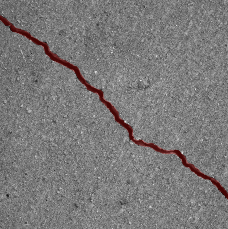
In this blog post, I will walk you through the process of using a pre-trained segmentation model from LandingAI to analyze crack images. The goal is to generate a segmentation mask and then calculate both the length and the largest perpendicular width of the detected crack. This technique is particularly useful in structural analysis, where accurate measurement of crack dimensions is crucial for assessing damage.
Overview of the Workflow
The process involves three key steps:
- Using LandingAI's LandingLens to create a segmentation model that can identify cracks in images.
- Applying the model to a crack image to obtain a segmentation mask.
- Using mathematical algorithms to calculate the crack's length and the largest perpendicular width from the segmentation mask.
Step 1: Building the Segmentation Model
LandingAI provides a platform called LandingLens, which allows you to train machine learning models on custom datasets. For this project, I trained a segmentation model on labeled crack images. The model learns to identify and segment cracks from the rest of the image. After training, the model is deployed to predict segmentation masks for new images.
Step 2: Getting the Segmentation Mask
Once the model is trained, we use it to predict the segmentation mask of a given crack image. The mask is a binary image where pixels belonging to the crack are marked in one color (e.g., white), and all other pixels are marked in another color (e.g., black). Below is the Python code that uses the LandingAI predictor to get the segmentation mask:
    predictor = Predictor("your-model-id", api_key="your-api-key")

    uploaded_file = st.file_uploader("Upload crack image")
    if uploaded_file is not None:
        image = Image.open(uploaded_file).convert("RGB")
        seg_pred = predictor.predict(image)
        color_dict = {"crack": "red"}
        image_with_preds = overlay_predictions(seg_pred, np.asarray(image),
                                               {"color_map": color_dict})
        st.image(image_with_preds, caption="Segmentation Predictions")

        flattened_bitmap = decode_bitmap_rle(seg_pred[0].encoded_mask,
                                             seg_pred[0].encoding_map)
        seg_mask_channel = np.array(flattened_bitmap, dtype=np.uint8)
                             .reshape(image.size[::-1])
        seg_mask_channel *= 255
This code snippet uploads an image, uses the predictor to generate a segmentation mask, and then displays the mask on the original image.
Step 3: Calculating Crack Length
With the segmentation mask in hand, we can now calculate the crack's length. The crack's length is determined by tracing the longest continuous path within the crack segment using the following method:
    def extend_line_to_binary(start_point, end_point, binary_image, org_image):
        # Calculate slope and intercept of the line
        if end_point[0] - start_point[0] != 0:
            slope = (end_point[1] - start_point[1]) / (end_point[0] - start_point[0])
        else:
            slope = float("inf")

        if slope == 0:
            slope = 0.001

        # Extend the line until it reaches the first point in the binary image
        rows, cols = binary_image.shape[:2]

        # Extend line in the negative direction
        extended_start_point = start_point
        for col in range(int(start_point[1]), -1, -1):
            row = int(start_point[0] + (col - start_point[1]) / slope)
            if row >= rows - 2:
                break
            if row >= 0 and row < rows and binary_image[col, row] != 0:
                extended_start_point = (row, col)
                break

        # Extend line in the positive direction
        extended_end_point = end_point
        for col in range(int(start_point[1]), cols - 1):
            row = int(start_point[0] + (col - start_point[1]) / slope)
            if row >= 0 and row < rows and binary_image[col, row] != 0:
                extended_end_point = (row, col)
                break

        distance = math.dist(extended_start_point, extended_end_point)
        return distance
This code calculates the length of the crack in pixels by extending a line along the crack's centerline and measuring the distance between the endpoints.
Step 4: Calculating Crack Width
Next, we calculate the crack's largest perpendicular width. This involves finding the medial axis of the crack, which represents the centerline, and then determining the maximum distance from the medial axis to the crack's boundary. Here's how this is done:
    def width(contours, seg_mask_channel, final_img, new_arr):
        delta = 3
        new_im = seg_mask_channel

        test_arr = np.array(np.zeros_like(seg_mask_channel), dtype=np.uint8)
        cv2.drawContours(test_arr, [max(contours, key=cv2.contourArea)], -1,
                         255, thickness=-1)

        medial, distance = medial_axis(test_arr, return_distance=True)

        # Get the maximum width from the medial axis
        max_idx = np.argmax(distance)
        max_pos = np.unravel_index(max_idx, distance.shape)
        coords = np.array([max_pos[1] - 1, max_pos[0]])

        # Intersect orthogonal with crack and get contour
        orth = np.array([-vector[1], vector[0]])
        orth_img = np.zeros(final_img.shape, dtype=np.uint8)
        cv2.line(orth_img, tuple(coords + orth), tuple(coords - orth),
                 color=255, thickness=1)
        gap_img = cv2.bitwise_and(orth_img, new_im)

        gap_contours, _ = cv2.findContours(np.asarray(gap_img), cv2.RETR_EXTERNAL,
                                           cv2.CHAIN_APPROX_SIMPLE)
        width_pixels = max(distance)
        return width_pixels
This code calculates the largest width by finding the maximum distance from the medial axis (centerline) of the crack to its boundary. The orthogonal line drawn at this point intersects the crack, and the width is determined by the distance between these intersection points.
Final Step: Converting Pixels to Physical Measurements
The final output of this analysis is in pixels. To convert these pixel measurements to real-world units (e.g., inches), we use a calibration step where we define the conversion factor from pixels to inches based on a known reference in the image.
Once the length and width in pixels are calculated, they are divided by this conversion factor to get the crack's dimensions in inches:
    st.write(
        "Predicted crack length in inches: "
        + str(length_pixels / 2 / st.session_state.inch_to_pixels)
    )
    st.write(
        "Predicted crack width in inches: "
        + str(width_pixels / 2 / st.session_state.inch_to_pixels)
    )
Conclusion
Using LandingAI to segment crack images and applying mathematical algorithms to measure crack dimensions can significantly improve the accuracy and efficiency of structural assessments. This approach automates the detection and measurement process, reducing the potential for human error and providing precise measurements that are critical for maintenance and safety evaluations.
Back to Blog